Shortcuts for Fixture Design

Fixtures are a necessary evil. Make designing them easier.

Welding fixtures can be expensive and complicated – and sometimes a product of simple luck and flaw. For manufacturers, the question is often “How fast can I get a fixture, at what cost and for what return?”. In this just-in-time (JIT) world, short runs are becoming common. So, when fixturing can be done in part or in total using a quick and cheap manufacturing process, bidding on such jobs becomes attractive. This is where technology comes in. Creatively inserting a little technology into your process can absolutely increase your efficiency.


Computer versus Traditional

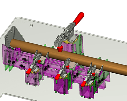
For some time, software-derived fixturing has played a part in chip-cutting applications. Mainstream Solid-Based CAD systems have enabled tooling designers to use solid body subtraction to create a fixture model for any given manufacturing process. Depending on the component to be fixtured and the CAD system, this process can be quick and easy or not much better than a traditional, manual extrapolation using desired contact points, etc. Time to develop a fixture and the accuracy of the manufacturing are part of the efficiency equation, as is controlling material and conventional hard-tooling costs.

Adapting Existing Processes for Fixturing

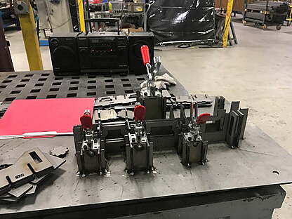
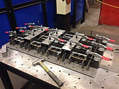
Hard tooling for traditional fixtures often depends on costly milling and other “non-sheet metal” processes. So, how can this be minimized? The simple answer is to marry the processes and machinery you already have‒ lasers, waterjets, punch presses, etc. ‒ to the appropriate CAD system.
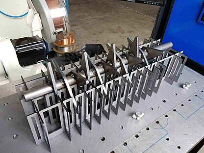
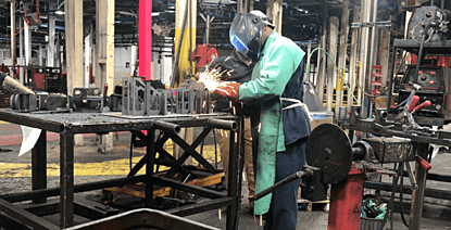
Smarter Welding

Historically, robotic welding is far more cost-effective in long run production than manual. But again, JIT demands more flexibility and thus, shorter runs. Although costs per part increase with short runs, the efficiency of robotic welding seems obvious. 


While “teach” methods for programming the robot remain the norm and allow for repeatability in small-batch runs, they present challenges when it comes to the speed of fixturing, leaving you to:


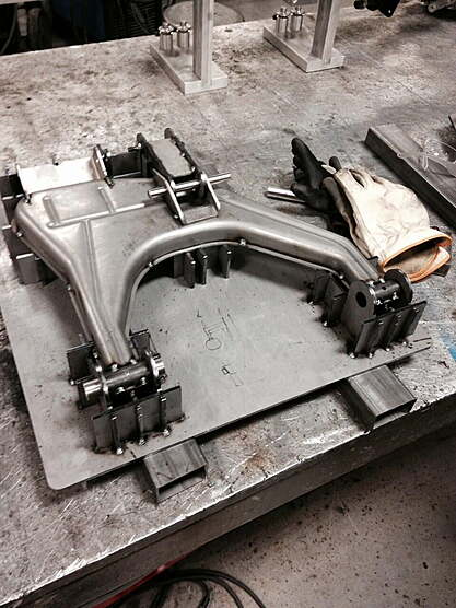
  • Conduct a short run without a robot, using a precious manpower to do the welding and make or source an expensive fixture.
  • Conduct a short run with a robot sitting idle while an expensive fixture is made or sourced.


Thanks to modern technology, you can cut the hard costs out of both processes by adding a software application to efficiently create a fixture and ultimately increases the profitability of the job.


Let’s say you have a short-run, repeat batch order that happens every three months. You may judge the time needed to fixture and program the part using traditional robotic techniques too time consuming and revert to manual welding. However, by using a computer-generated fixture and subsequently saving the robot program, you can drastically cut design time when the order is repeated, making the robotic method far more attractive. Robots aside, creating fixtures in part or entirely with software can also increase the efficiency of a manual welding process.


Gearing Up for Repeatability or Upstream Changes

Depending on the robot model or whether there’s access to a probing arm, you can accurately relocate a fixture on the welding station table by using just three sets of XYZ coordinates, positioned exactly the same way on the computer model as they are on the actual fixture and part. This enables you to use the model to easily calculate the skew and then mathematically adjust at the robot.

So, what if you encounter a slight upstream change requiring adjustment to the contact points between the fixture and the part? Simply retrieve the original CAD model and make discreet geometric changes to your fixture and part as needed. In most instances, the affected fixture component can easily replace the previous one.


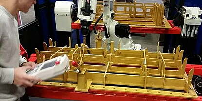
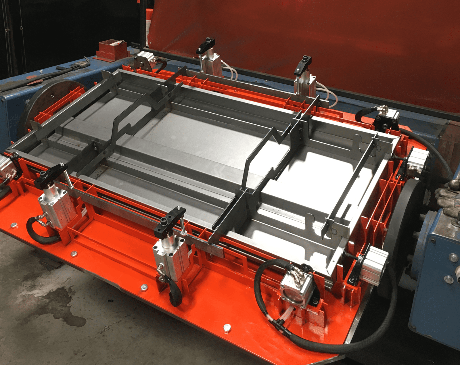
Automating Fixture Design and Assembly 

Beyond the value software can bring to traditional machining applications, it can also add efficiency to the total fabrication process. In fact, the right software can uncover uses for what you already have in your shop today.

Consider a CAD system focused on design and assembly of welding fixtures for cutting from flat sheet metal. Like a 3D jigsaw, fixture components must interlock to create a part fixture. While you could use SolidWorks™ or similar, it would require time, effort and most likely some subsequent manual editing.

CAD software enables you to automate assembly by importing component parts into the system as solid bodies. Using a step-by-step wizard interface, all the necessary inputs are provided, including the fixture material gauge, oversize, offsets, base plate bolt holes and most importantly, the positions of the upright blades, designated as X and Y. These blade positions are computed using a hybrid cross-section of the solid bodies present, from Z0 upwards.

In essence, the upper edge profile mates to the underside and vertical Z direction edges of the solid parts, creating a cradle into which the part assembly is placed. Along with the ability to import standard clamp CAD files (De-Sta-Co, etc.), it is possible to model the complete part and fixture assembly. 

Advanced options such as “gripper points” address model-to-real world inconsistencies. For example, a blade profile can be offset and small radii equal to the offset can be placed at intervals along the edge; these can then be manually ground down to accommodate for interference issues.

Or in the case of formed bends in a press-brake operation – where the model is perfect, but the material itself isn’t – automated functions can reduce excessive interference between the fixture and the bend radius. A good automated system can also accommodate for soft materials such as aluminum by including holding methods to reduce surface scratches or help you define location pins for tight-tolerance parts. Providing functions to create a skeletal fixture by removing unnecessary material from the fixture assembly not only creates a lighter fixture but help with the dissipation of heat accumulated within the fixture assembly by the welding process. With traditional fixtures, this build up can result in unpleasant product variance over the course of the working day.

The best part about a design and assembly software is that your model can be simply laid flat in XY and exported to DXF for later profiling of your existing machinery.


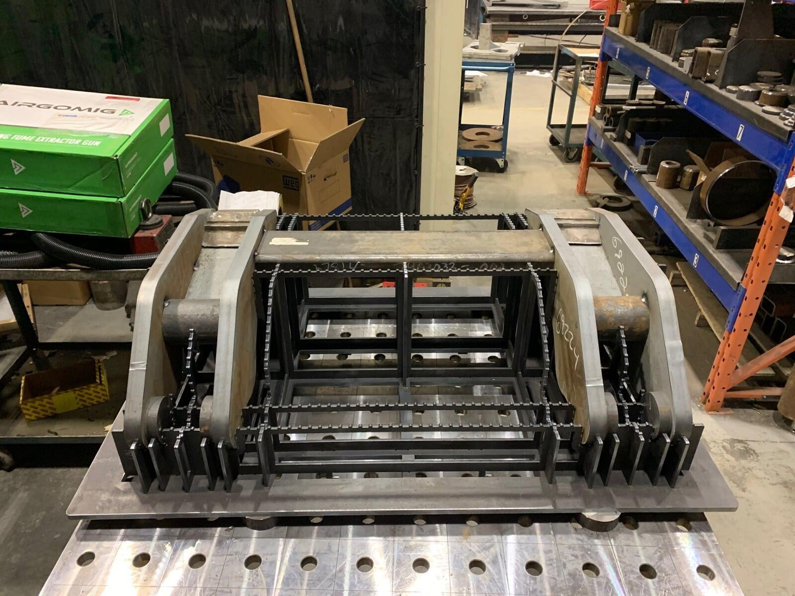
Standardization, Reducing Storage Space

Software-generated fixturing can provide your shop with a standard methodology. As a result, you may find yourself using the same clamp manufacturer and likewise, the same approach to for many fixture designs. 

For example, in robotic welding, a pre-set table bolt-hole array is often present. Where appropriate, a generic “base plate” can be attached to the table with “tab slots” at a standard pitch interval. Fixture blades can then be inserted and locked to the base plate using an optional “clip foot” design, making assembly and disassembly of the fixture quick and easy. Even if the whole base plate and blade assembly is removed between jobs, the process is relatively simple and efficient. 

For those with a head and tailstock arrangement (an A or B axis), being able to explicitly define the base plate dimensions and bolt hole locations is particularly useful, as these parameters can be saved as the default for subsequent fixture development runs. Easily adding access apertures to the base plate for inverted or tilted welding operations is also beneficial.

Using a geometric design such as a “clip tab” mechanism eliminates the need to spot-weld your fixture for rigidity. It can be disassembled and stacked flat, saving space and reducing the need for storage expansion.


Staying Flexible for Simple or Complex Design

To a large degree, the method and simplicity (or complexity) of fixture design using a “blade approach” is determined by the user’s imagination or requirements. It may be that a part needs a multi-stage fixture approach, with the sub-assemblies being incrementally welded together across the fixture at appropriate “cradle” locations. Alternatively, it may be desirable to have the same part in multiple cradle positions – or a combination of both – or even a range of dissimilar parts. Whatever the case, more or less any part assembly can easily be accommodated – from the small to the very large, from pipe assemblies to enclosures.

So, How Much Can Be Saved?

Feedback suggests software can result in a 75 percent savings in time alone. As far as cost savings, it will vary by how software has been employed in your process. If software makes use of scrap for fixtures, the actual production costs can be quite minimal. 

Costs can also vary by the lifespan of the fixture. The precise nature of the software gives you the flexibility to use cheap or scrap/remnant materials for short-run use or to use more-expensive, longer-lasting metal for frequently used fixtures. 

In the case of a trailer manufacturer, conventional costs were approximately $8000. By employing software-developed fixturing they slashed hard costs down to about $350. 

The cost to purchase software can often be justified by what you’ll save by converting just a few traditional fixture runs into computer-assisted ones. Suffice to say, a well-adapted software solution can definitely impact your bottom line -- how much depends on how creatively you employ it.


Top